12 V
Source voltage
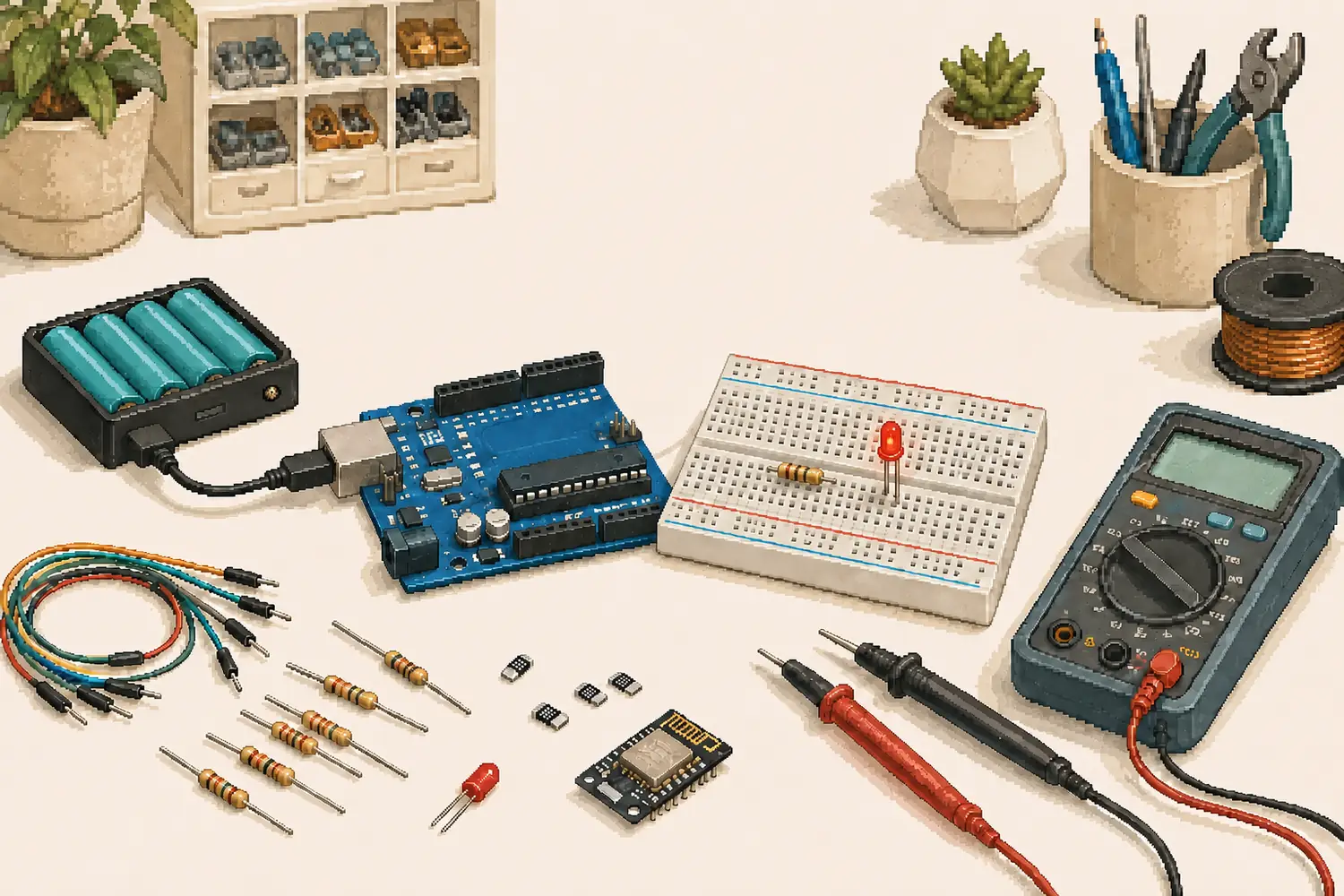
In 2012, I bought my first Arduino kit. It gave my fascination with electronics somewhere practical to go. Voltage, current, and resistance stopped being symbols on a page and became things I could change, measure, get wrong, and eventually understand.
I kept playing. One project led to another, and the collection grew with them. I now have a huge arsenal of components of different kinds, enough that I could potentially create almost anything I would like, given the time.
Time is the scarce component. Other parts of life arrive, take their share, and leave the workbench waiting. Electronics has become a real passion that I rarely get enough time to explore anymore. The interest has not gone away. It has simply had to live between everything else.
That is why I wanted to return to this old post. It began as a compact explanation of Ohm’s law, power, and resistance. I wanted it to become something I would actually reach for when an evening finally opened up: a small set of tools that removes the first bit of friction between an idea and a working circuit.
These calculators are not a replacement for a multimeter, a datasheet, or testing the real circuit. They are a way back in.
The first tool keeps the relationships between voltage, current, resistance, and power in one place. Choose the two values you know and it calculates the other two. The LED helper accounts for forward voltage, which matters when choosing a current-limiting resistor.
It also includes first-order passive RC filters. A low-pass filter lets slower changes through while reducing higher-frequency noise. A high-pass filter does the opposite, blocking DC and slower changes while allowing faster changes through. The diagrams show why the output point matters, and the response graph shows what happens around the cutoff frequency.
Battery life is where a simple calculation can become misleading. A device that draws 20 mA while awake and 50 µA while sleeping still needs one more piece of information: how often it wakes up. One hundred milliseconds every minute is a very different load from one hundred milliseconds every second.
The estimator turns that duty cycle into average current and power. It works in watt-hours when the battery voltage and load voltage differ, includes editable efficiency and usable-capacity assumptions, and shows both an ideal maximum and a more cautious planning estimate.
The presets are starting points, not promises. Battery capacity changes with load, cutoff voltage, temperature, age, and chemistry. Peak current and voltage sag can also stop a project long before the arithmetic says the stored energy is gone.
Open the Battery Runtime estimator on its own
The third tool is for the small parts that always seem obvious until one is already between the multimeter probes. It reads four-band and five-band axial resistor colors, decodes common SMD markings, and finds the nearest preferred resistor values when the exact number is not available.
The visualization changes with the code. It also keeps the written band names and decoded value visible, so color is never the only way to identify a part. Very small SMD packages may be unmarked, and unusual manufacturer codes still need their datasheet, but the common cases are here.
The four quantities at the center of these tools are voltage (V), current (I), resistance (R), and power (P).
[ V = I \times R ]
[ P = V \times I ]
[ R = \frac{V}{I} ]
If a 12 V source drives a 6 Ω resistive load, the current is 2 A and the load dissipates 24 W. Knowing any valid pair lets the calculator rearrange the equations and find the rest.
The resistor in series with an LED does not normally have the full supply voltage across it. The LED takes its forward-voltage share first. For a 5 V supply, a 2 V LED, and a 330 Ω resistor, the expected current is about 9.1 mA:
float supplyVoltage = 5.0;
float ledForwardVoltage = 2.0;
float resistance = 330.0;

float resistorVoltage = supplyVoltage - ledForwardVoltage;
float current = resistorVoltage / resistance;

Serial.println("Current through the LED is " + String(current) + " A");
Forward voltage varies between LEDs and changes with current and temperature. Use the component datasheet, choose a conservative current, then measure the real circuit.
For a 5 V motor drawing 0.5 A, the electrical input power is 2.5 W:
float voltage = 5.0;
float current = 0.5;
float power = voltage * current;

Serial.println("Electrical input power is " + String(power) + " W");
That is electrical input, not mechanical output. Motors also have startup and stall currents that can be much higher than their unloaded running current.
If I know the voltage across a component and the current through it, I can calculate its resistance. A current sensor needs its own transfer function handled correctly. For example, the ACS712 output sits near half its supply voltage at zero current, so that offset must be measured or calibrated before applying the sensor sensitivity. The exact ADC reference and ACS712 variant matter too. Allegro ACS712 datasheet
float adcReference = 5.0;
float zeroCurrentVoltage = 2.5; // Calibrate this on the real circuit
float sensitivity = 0.185;      // V/A for the ACS712 5 A variant
float voltageAcrossComponent = 5.0; // Measure this separately

float sensorVoltage = analogRead(A0) * (adcReference / 1023.0);
float current = (sensorVoltage - zeroCurrentVoltage) / sensitivity;
float resistance = voltageAcrossComponent / abs(current);

Serial.println("Calculated resistance is " + String(resistance) + " ohms");
Do not use resistance mode on a powered circuit. For an ordinary loose resistor, disconnect power and measure it directly with the meter instead.
For a device that alternates between awake and sleep states, average current begins with the fraction of each cycle spent awake:
[ d = \frac{t_{awake}}{t_{cycle}} ]
[ I_{average} = I_{awake}d + I_{sleep}(1-d) ]
If the battery and load operate at the same voltage with no conversion losses, capacity in mAh divided by average current in mA gives an ideal runtime in hours. When the voltages differ, the useful comparison is energy in watt-hours, adjusted for conversion efficiency and the usable fraction of the battery.
For long-lived sensor projects, the board around the microcontroller can matter as much as the chip. Regulators, LEDs, pull-ups, and USB interfaces may continue drawing current during deep sleep. Measure the complete assembled device before trusting a multi-year estimate.
For an ideal first-order passive RC filter, the cutoff frequency and time constant are:
[ f_c = \frac{1}{2\pi RC} ]
[ \tau = RC ]
At the cutoff, the output amplitude is about 70.7% of the pass-band value, which is approximately −3.01 dB. A low-pass takes its output across the capacitor. A high-pass takes its output across the resistor. Real source and load impedances become part of the network and can move the result. Analog Devices RC filter introduction
Resistor color and marking codes are standardized in IEC 60062. The tools cover the common cases, but the component datasheet remains the final reference when a marking is ambiguous.
The boxes of components are still here. So is the curiosity that filled them. I may not get as many evenings with electronics as I once imagined, but when the time appears, I no longer have to begin by searching for the same formulas again. I can begin with the thing I wanted to build.